
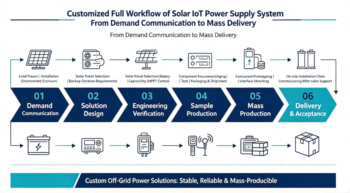
As smart agriculture, forest fire prevention, water conservancy monitoring, and remote communication base stations become increasingly prevalent, countless IoT field terminals face critical pain points: the high cost and logistical impossibility of grid power cabling, coupled with severe risks of power outages. Off-grid solar IoT power supply systems have emerged as the definitive solution. However, standardized solar products often fail to accommodate the unique power consumption, spatial constraints, and extreme environmental demands of different scenarios. Consequently, customized development is surging.
Unfortunately, many procurement managers and system integrators lack a clear understanding of the complete customization process. This knowledge gap frequently leads to mismatched solutions, endless sample revisions, delayed mass production, and high failure rates in outdoor deployments. This comprehensive guide breaks down the entire lifecycle of custom solar IoT power systems—from initial requirement communication and solution design to prototyping, mass production, and after-sales support. It serves as a strategic roadmap for integrators to streamline development, avoid costly pitfalls, and ensure successful project execution.
1. Deep Requirement Communication: The Foundation of Customization
The root cause of most system failures lies in incomplete initial requirement gathering. Requirement communication is not merely about confirming power capacity; it requires collecting data across four critical dimensions: device parameters, environmental conditions, installation constraints, and compliance standards.
Before designing a solution, manufacturers must verify core information with integrators and end-users. First, evaluate the IoT terminal’s power parameters: the static and peak power consumption of sensors, cameras, and gateways, as well as their daily operating hours. Distinguishing between continuous power supply and intermittent wake-up modes is vital, as this directly dictates the solar panel wattage and lithium battery capacity.
Next, assess the natural environment: latitude, annual peak sun hours, winter minimum temperatures, coastal salt spray exposure, mountain frost, and dust storms. Low temperatures significantly reduce lithium battery discharge capacity, while salt spray environments demand higher anti-corrosion ratings.
Physical installation limits must also be confirmed, including pole dimensions, equipment cabin space, maximum solar panel dimensions, and the need for flexible modules. Additionally, clarify electrical specifications (output voltage, communication interfaces, reverse-charge and overvoltage protection), project timelines (sample delivery, initial batch quantity, replenishment plans), and compliance requirements (CE, RoHS, IEC certifications).
Many projects fail because they only specify “12V power supply” while ignoring nighttime endurance during continuous cloudy days, resulting in system shutdowns. A comprehensive requirement checklist is the primary prerequisite for a successful project.
2. Solution Simulation and Structural Design: Delivering Actionable Technical Plans
Once requirements are gathered, the process moves to the design phase, divided into electrical power matching simulation and mechanical structural design.
Electrical simulation is the core. Engineers utilize PV-storage simulation models based on local solar irradiance data to match PV module power, MPPT charge controller specifications, and LiFePO4 battery capacity to calculate continuous cloudy-day endurance. For example, a forest fire camera requiring 7 days of uninterrupted power during rain will necessitate larger battery storage or higher-efficiency panels. Control strategies, such as sleep-mode voltage regulation and low-voltage protection thresholds, are also defined.
The structural solution depends on the installation scenario. PET epoxy panels are suitable for indoor or short-term testing; ETFE flexible modules are ideal for curved surfaces or portable devices; while tempered glass laminated panels are prioritized for long-term, unattended outdoor stations. Battery cabin waterproofing, cable specifications, and terminal models are also designed, distinguishing between IP65 basic waterproofing and IP67 high-protection schemes.
Upon completion, formal technical documentation is generated, including system configuration lists, dimension drawings, electrical schematics, power simulation reports, and appearance renderings. Both parties must review and lock the technical baseline to prevent future modifications.
3. Prototyping and Laboratory Testing: Exposing Potential Defects Early
After technical confirmation, sample production begins. Custom solar samples are not simple assemblies; they serve to validate risks.
Factories manufacture PV components, battery packs, and controller housings according to approved drawings. After assembly, basic in-house tests are conducted: charge voltage stabilization, high/low voltage protection, and waterproof spray tests. Samples are then delivered to the client for field pilot testing.
Field testing includes both laboratory simulation and on-site trial runs. Labs can simulate continuous rain and extreme temperatures to test battery discharge performance. However, on-site testing is paramount. The entire system is deployed to the actual project site for 15–30 days to record sunny-day generation, nighttime consumption, and rainy-day endurance.
Common issues exposed during testing include insufficient winter generation due to undersized PV panels, improper low-voltage protection thresholds, casing water leakage from outdoor temperature fluctuations, and rapid cable connector aging. All issues are compiled to optimize structures and adjust electrical parameters until the prototype meets 24/7 outdoor standards. Proceeding to mass production without field testing is a massive project risk.
4. Mass Production Preparation and Scaled Manufacturing
Once samples pass acceptance testing, the project enters mass production. Pre-production preparation includes material confirmation, tooling creation, and Standard Operating Procedure (SOP) formulation.
Procurement departments bulk-order solar cells, lithium battery cores, MPPT PCBs, housings, sealants, and cables based on the locked solution. Custom components often have longer lead times than standard products, requiring advanced scheduling to prevent delays.
Production involves three processes: PV module manufacturing (lamination/epoxy, cutting, wiring), energy storage assembly (series/parallel connection, BMS installation), and full system integration (combining controllers and waterproof housings).
Standardized quality control accompanies the entire process: Incoming Quality Control (IQC), semi-finished product power-on testing, finished product aging tests, and appearance/waterproof re-inspection. Every unit undergoes over 4 hours of power-on aging to eliminate wiring defects and ensure high yield rates. For large orders, factories can arrange phased production to meet staggered delivery schedules.
5. Final Inspection, Packaging, and Logistics Delivery
Post-production, all finished products undergo final inspection against unified standards for electrical parameters, labeling, and waterproof sealing. Export orders include packing lists, certificates of conformity, certification documents, and user manuals.
Field solar products are prone to physical damage. Tempered glass panels require foam corner protectors and reinforced cartons; flexible ETFE components need scratch protection; and lithium batteries must be packaged separately according to dangerous goods transport regulations. Logistics tracking numbers are provided, with bulk cargo arranged for full-truck transport and small samples prioritized via express delivery.
Upon arrival, clients conduct inventory checks. In case of transit damage, factories initiate rapid replacement protocols to safeguard project schedules.
6. On-Site Technical Support and Long-Term After-Sales Guarantee
Many mistakenly believe delivery marks the end of a project. In reality, IoT solar systems are electromechanical products where installation directly impacts lifespan. Reputable custom manufacturers provide comprehensive support: standard wiring diagrams, guidance on PV orientation/tilt, and correct battery connection sequences to prevent terminal damage.
During the warranty period, non-man-made faults are repaired or replaced. Continuous technical consultation is provided for project expansions or equipment upgrades. For long-term outdoor deployments, establishing maintenance archives to regularly clean panel dust and inspect terminal corrosion is highly recommended to maintain generation efficiency.
7. Customization Timeline Reference
| Process Stage | Typical Duration | Core Deliverables | Key Precautions |
|---|---|---|---|
| Requirement Communication | 1–3 Working Days | Requirement Collection Checklist | Ensure complete info on endurance, environment, and size limits |
| Solution Design & Simulation | 2–4 Working Days | Config List, Drawings, Simulation Report | Multi-party technical review; lock the plan to avoid changes |
| Prototyping & Testing | 7–15 Working Days | Physical Prototype, Test Report | Mandatory on-site trial run testing |
| Sample Revision & Optimization | 3–10 Working Days | Revised Drawings, Updated BOM | Document and confirm all changes in writing |
| Bulk Material Procurement | 7–20 Working Days | Raw Materials Warehoused | Custom materials have longer lead times; buffer is essential |
| Scaled Manufacturing | 5–12 Working Days | Complete Power Supply Systems | Synchronized power-on aging testing |
| Final Inspection & Shipping | 1–3 Working Days | Finished Goods, Full Documentation | Strict adherence to lithium battery transport regulations |
| After-Sales Support | Full Project Lifecycle | Wiring Guidance, Fault Resolution | Retain complete technical handover documentation |